Refrigeration Compressor Start-Up and Installation Checklist
Use this compressor installation checklist to verify wiring, oil, piping, brazing, evacuation, and first-run conditions before a refrigeration system starts.
Refrigeration Compressor Start-Up and Installation Checklist
A refrigeration compressor installation is only as reliable as the checks completed before the first start. Incorrect wiring, contaminated oil, poor brazing, trapped moisture, or an incomplete evacuation can lead to nuisance trips, poor cooling, lubricant damage, or early compressor failure.
This compressor installation checklist is intended for refrigeration service technicians, cold-room contractors, engineering installers, and spare parts teams handling compressor replacements. It covers the practical checks that should be completed before energizing a compressor and during the first run. Always verify the compressor manufacturer’s installation instructions, the system refrigerant, electrical data, oil requirements, pressure limits, and local safety rules before work begins.
Confirm the Compressor and System Match
A replacement compressor should not be selected by appearance or mounting dimensions alone. Confirm that its operating conditions are suitable for the refrigeration system and that the electrical and refrigerant requirements are compatible.
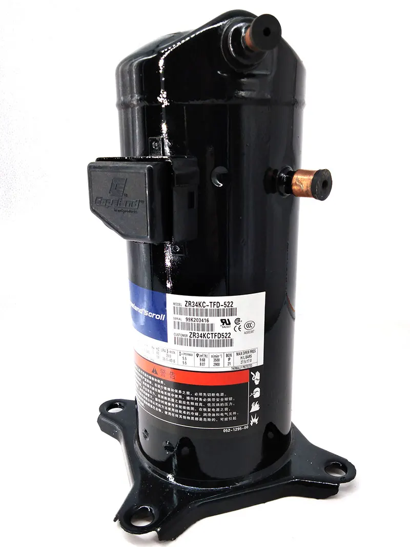
Check the following information on the compressor nameplate, technical documentation, or approved replacement data:
- Compressor model and application range
- Refrigerant type and system design conditions
- Rated voltage, phase, and frequency
- Motor protection and starting method
- Oil type and factory oil charge, where applicable
- Suction and discharge connection sizes
- Recommended operating envelope
- Mounting arrangement and vibration requirements
- Crankcase heater or other required accessories
A compressor may have similar connections to the original unit but still be unsuitable because of different voltage, refrigerant compatibility, displacement, oil, or operating limits. Distributors and replacement buyers should provide the complete compressor model and system details when requesting a substitute. Installers should compare the replacement against the approved technical data before removing the original unit.
Inspect the compressor before installation. Look for damaged terminals, cracked covers, bent connection tubes, loose mounting components, signs of oil leakage, or damage to the shell. Keep protective plugs in place until the piping is ready to connect. Opening the compressor too early can allow moisture and debris to enter the internal system.
Electrical and Wiring Checklist
Electrical errors are among the most serious risks during compressor start-up. The power supply, motor terminals, control circuit, protection devices, and grounding arrangement must all be checked with the power isolated.
Verify the power supply
Confirm that the available supply matches the compressor nameplate. Check voltage, phase, and frequency, and verify that the supply is appropriate for the motor starting method. A three-phase compressor requires correct phase identification and suitable protection. A single-phase compressor may require the specified relay, capacitor, or starting component.
Do not assume that a component from the old compressor can be transferred to the replacement. Starting devices, capacitors, overload protectors, relays, electronic modules, and terminal arrangements can vary between models with similar capacities.
Inspect terminals and connections
Before energizing the system, verify that:
- Motor terminals are connected according to the wiring diagram.
- Terminal screws and cable connections are correctly tightened.
- Cable sizes are suitable for the operating and starting current.
- Cable insulation is undamaged and protected from sharp edges.
- The compressor shell and electrical enclosure are properly grounded.
- Overload, phase, voltage, and short-circuit protection are correctly selected.
- Control wiring is separated and protected where required.
- Pressure controls and safety switches are connected to the correct circuit.
Use a suitable electrical meter to confirm continuity and the condition of the wiring. Insulation and winding tests should be carried out only in accordance with the compressor manufacturer’s instructions. Some electronic compressors and modules can be damaged by inappropriate testing procedures or test voltages.
Check the control sequence
Trace the control circuit before the start command is given. The high-pressure switch, low-pressure switch, oil protection, thermostat, controller, crankcase heater, and other safety devices should operate as intended. Confirm that the compressor cannot start under an unsafe pressure or temperature condition.
For three-phase motors, verify phase rotation where the compressor design requires it. Incorrect rotation can cause abnormal operation or fail to produce the expected pumping action. Follow the applicable compressor documentation and use the specified method for checking rotation.
Oil, Mounting, and Piping Checks
Oil protects the moving parts of the compressor, but the correct oil level and type depend on the compressor and refrigerant combination. Do not add oil simply because the compressor is new, and do not reuse oil from a failed or contaminated system without an approved procedure.
Confirm the oil requirement
Check whether the compressor is supplied with a factory oil charge and identify the specified oil type. If additional oil is required, use only the grade approved for the compressor and refrigerant. Mixing incompatible oils can affect lubrication, oil return, seals, viscosity, and system performance.
An oil charge should be measured rather than estimated. Excess oil can reduce heat-transfer performance and contribute to oil circulation problems. Too little oil can reduce lubrication and increase wear. If the previous compressor suffered a severe electrical or mechanical failure, the system may require cleaning, filter-drier replacement, and a specific oil management procedure before the replacement compressor is started.
Install the compressor correctly
Mount the compressor on the specified vibration isolators or mounting hardware. Keep the unit level and avoid forcing the connection tubes into alignment. Pipe stress transferred to the compressor shell or service connections can cause leaks and vibration problems.
Check that the compressor has sufficient clearance for electrical service, valve access, airflow, and future inspection. Keep wiring and tubing away from hot surfaces and moving components. Confirm that vibration isolators are installed consistently and that mounting fasteners are secure without being over-tightened.
Review suction and discharge piping
The piping layout must support refrigerant flow, oil return, service access, and safe operation. Inspect the suction line, discharge line, liquid line, accumulator, receiver, filter-drier, valves, and other components for correct direction and connection.
Pay particular attention to:
- Correct suction and discharge connections
- Pipe size and routing for the system application
- Adequate support to prevent vibration and movement
- Traps, risers, and oil-return arrangements where required
- Service valves in the correct operating position
- Protection against liquid refrigerant entering the compressor
- Clean, dry tubing with capped ends before installation
- Replacement of components damaged or contaminated during the repair
A compressor should not be used to pull a vacuum or clear debris from the pipework. Use proper recovery, evacuation, and charging equipment. Debris, moisture, and non-condensable gases can damage the compressor and reduce system performance.
Brazing and Evacuation Checklist
Good brazing practice and thorough evacuation are essential parts of compressor installation. A system that appears mechanically complete can still contain moisture, oxygen, nitrogen, brazing scale, or other contamination.
Prepare for brazing
Remove protective caps only when each connection is ready. Clean the tube ends and fittings, keep the inside of the tubing free from dirt, and make sure the joint is correctly supported. Use the approved brazing material and heating procedure for the tube and fitting combination.
When brazing refrigeration pipework, use an appropriate inert-gas purge where required by the procedure. A controlled purge helps limit internal oxidation and scale formation. Keep the purge flow and heating method within the equipment and filler-material requirements; excessive gas flow can disturb the joint and inadequate preparation can leave contamination inside the system.
Protect the compressor, valves, wiring, insulation, and nearby components from heat. Do not direct the flame toward the compressor shell, electrical terminals, service valves, or sensitive components. After each joint cools, inspect it for complete penetration, pinholes, cracks, excessive filler, and signs of overheating.
A visual inspection does not replace a leak test. Pressurize the system with the approved dry test gas and use a suitable leak-detection method. Never use oxygen or another unsuitable gas for pressure testing. Test pressure must remain within the limits of the system components and the applicable safety requirements.
Evacuate the system correctly
Evacuation removes air and moisture before charging and starting the compressor. Connect the vacuum pump through properly sized hoses and a suitable manifold or valve arrangement. Long, narrow hoses and restrictive service ports can make the gauge reading appear acceptable while the system still contains moisture or pressure pockets.
Before evacuation, confirm that the system is leak-tight and that the vacuum equipment is in good condition. Use a calibrated vacuum measuring device positioned to show the pressure in the system, not only the pressure at the pump. The required vacuum level and standing-vacuum procedure should follow the compressor or system manufacturer’s instructions.
After reaching the specified vacuum, isolate the system and observe whether the pressure remains stable. A rising pressure can indicate a leak, moisture evaporation, trapped refrigerant, or a problem with the test setup. Find and correct the cause before charging. Repeating the evacuation without correcting a leak will not solve the problem.
Keep the system isolated from ambient air after evacuation. Charge the specified refrigerant using the approved method and equipment. Avoid liquid entry into the compressor unless the system procedure specifically permits it under controlled conditions.
Start-Up and First-Run Inspection
The start-up should be controlled and observed rather than treated as a simple power-on step. Record the initial conditions so that abnormal behavior can be identified quickly and the service team has a useful commissioning record.
Before the start command, confirm:
- All service valves are in the correct position.
- The refrigerant charge is appropriate for the system procedure.
- The compressor crankcase heater, where fitted, has operated for the required period.
- The suction and discharge lines are connected correctly.
- Electrical covers and terminal guards are installed.
- Pressure controls and safety devices are active.
- The evaporator and condenser airflow or water flow is available.
- Fans, pumps, valves, and controllers are ready to operate.
- No tools, caps, packaging, or loose materials remain near moving or hot parts.
At start-up, observe the compressor and system continuously. Check for unusual vibration, knocking, rapid cycling, abnormal noise, oil leakage, refrigerant leakage, and unexpected pressure behavior. Verify that the compressor is responding to the control signal and that the condenser and evaporator are operating as intended.
Measure and record the relevant readings for the application, such as supply voltage, operating current, suction pressure, discharge pressure, suction temperature, discharge temperature, and superheat or subcooling where applicable. Compare the readings with the equipment manufacturer’s operating guidance and the design conditions. A single pressure reading does not prove that the system is correctly charged or operating safely.
Stop the compressor if there is evidence of incorrect rotation, severe vibration, loss of lubrication, abnormal noise, rapid pressure rise, electrical overheating, or another unsafe condition. Isolate the power and investigate the cause before attempting another start. Repeated short starts can add stress to the motor and system, so verify the control settings and allow appropriate equalization where required.
Close-Out Checklist for the Service Record
After the system reaches stable operation, inspect all accessible joints, service ports, electrical connections, and mounting points again. Confirm that insulation is complete, pipe supports are secure, and panels are correctly fitted.
A useful commissioning record should include:
- Compressor model and serial information, where available
- Refrigerant and oil details
- Electrical supply and measured operating current
- Pressure and temperature readings
- Leak-test and evacuation results
- Components replaced during the repair
- Safety-control operation
- Start-up observations and any adjustments made
- Date, technician, and installation location
This information helps distributors and repair companies support future warranty, troubleshooting, and replacement decisions. It also gives installers a clear baseline if the system later develops a performance issue.
A reliable compressor installation depends on preparation across the entire circuit. Matching the compressor correctly, checking the wiring, protecting the oil system, completing clean brazing, proving the system is leak-tight, evacuating thoroughly, and observing the first run can prevent many avoidable failures. Use the checklist alongside the exact compressor documentation and the requirements of the refrigeration system being commissioned.
FAQ
What should be checked before starting a refrigeration compressor?
Confirm the compressor and refrigerant match, verify voltage and phase, inspect wiring and grounding, check oil requirements, review suction and discharge piping, leak-test the system, complete evacuation, confirm the refrigerant charge, and make sure safety controls and system airflow are operating.
How important is evacuation during compressor installation?
Evacuation removes air and moisture from the refrigeration circuit before charging. The system should be leak-tight, evacuated to the manufacturer’s specified condition, isolated, and monitored for pressure rise. A rising pressure can indicate a leak, remaining moisture, or a problem with the test setup.
Should oil be added to a new refrigeration compressor?
Not automatically. Check whether the compressor already contains a factory oil charge and confirm the required oil type for the compressor and refrigerant. Add oil only when the system procedure requires it, and measure the amount rather than estimating.
What should technicians observe during the first compressor run?
Monitor vibration, noise, oil or refrigerant leakage, operating current, suction and discharge pressures, temperatures, control response, and the operation of fans or pumps. Stop the compressor if there is severe vibration, abnormal noise, overheating, incorrect rotation, or unsafe pressure behavior.
Buyer Next Step
Move from research to sourcing with a category shortlist, relevant product examples, and a quote request channel.